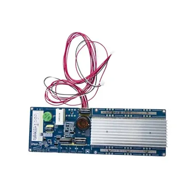
High Frequency Inverter Circuit Diagram
Simple High frequency inverter circuit diagram and PCB layout. The inverter provide the power output up to 500 watts.
Simple High frequency inverter circuit diagram and PCB layout. The inverter provide the power output up to 500 watts.

There''s a much easier and efficient way of making a 1 kva inverter circuit using the following 4017 PWM version circuit. Since the PWM is created

The 7 simple inverter circuits for newcomers explained in the following paragraphs concerns easy to build designs and as economical as you
This article provides an overview of high-frequency inverter topologies, design considerations, applications, and advantages versus traditional lower frequency inverters.

High-frequency inverters play a crucial role in modern power conversion by efficiently transforming DC to AC at elevated switching frequencies. Their working principle relies on rapid switching, high
We would like to show you a description here but the site won''t allow us.
What is a High-Frequency Inverter? A high-frequency inverter is an electrical device that converts direct current (DC) into alternating current (AC) at
To produce a sine wave output, high-frequency inverters are used. These inverters use the pulse-width modification method: switching currents at high frequency, and for variable periods of time.
Want to build your own high-frequency 1000W inverter but unsure where to start? This guide breaks down the essentials—from component selection to efficiency optimization—while aligning with
In many applications, it is important for an inverter to be lightweight and of a relatively small size. This can be achieved by using a High-Frequency Inverter that involves an isolated DC-DC stage (Voltage
PDF includes complete article with source references.
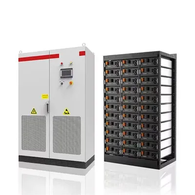
Download EMS datasheets, pricing guides, and microgrid controller specifications.
Via Monte Rosa, 91
20149 Milan, Italy
Italy (Sales): +39 06 4529 8732
Italy (Support): +39 331 275 4896
Mon-Fri: 9:00 AM – 6:00 PM (CET)