Schematic diagram of high voltage cascade energy storage system
Schematic diagram of a battery energy storage system (BESS) operation, where energy is stored as chemical energy in the active materials, whose redox reactions produce electricity when
Schematic diagram of a battery energy storage system (BESS) operation, where energy is stored as chemical energy in the active materials, whose redox reactions produce electricity when
Figure 2 shows the four-quadrant operation diagram of the high-voltage cascaded energy storage system, where U S is the grid-side voltage, U I is the valve-side voltage, and I L is...
Figure 2 shows the four-quadrant operation diagram of the high-voltage cascaded energy storage system, where US is the grid-side voltage, UI is the valve-side voltage, and IL is the inductor
The utility model discloses a high-voltage direct-hanging type cascade energy storage unit which comprises an inversion unit and an expansion unit, wherein the inversion unit comprises an
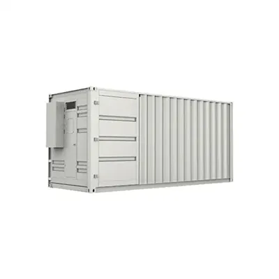
Figure 2 shows the four-quadrant operation diagram of the high-voltage cascaded energy storage system, where U S is the grid-side voltage, U I is the valve-side voltage, and I L is the inductor current.

Figure 2 shows the four-quadrant operation diagram of the high-voltage cascaded energy storage system, where US is the grid-side voltage, UI
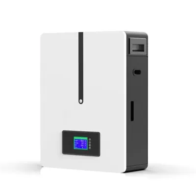
Fig.1 shows the high voltage cascaded storage system topology structure. Besides the battery and switch device, each phase also contains a charging circuit, filter
First, operational features and principle of the CESS was outlined. Then, long-term operations of the CESS and cascade hydropower system were, respectively, optimized using a
Aiming at the defects in the prior art, the utility model provides a high-voltage direct-hanging type cascade energy storage unit to solve the technical problems mentioned in the...
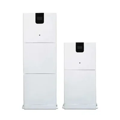
The cascaded high-voltage energy storage system can be directly connected to the grid without going through boosting transformer, with voltage levels ranging from
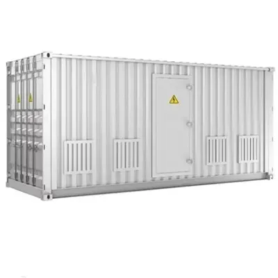
Fig.1 shows the high voltage cascaded storage system topology structure. Besides the battery and switch device, each phase also contains a charging circuit, filter inductor, etc.

They cascade to generate the desired output current and each dual-boost/buck converter has its own dc source which is especially suitable for the viable battery storage units without ultra-high-voltage
The cascaded high-voltage energy storage system can be directly connected to the grid without going through boosting transformer, with voltage levels ranging from 6kV to 35kV.

The research results provide a comprehensive theoretical and practical reference for the optimal design of high-voltage cascaded energy storage systems and contribute to promoting their application in the
PDF includes complete article with source references.
Download EMS datasheets, pricing guides, and microgrid controller specifications.
Via Monte Rosa, 91
20149 Milan, Italy
Italy (Sales): +39 06 4529 8732
Italy (Support): +39 331 275 4896
Mon-Fri: 9:00 AM – 6:00 PM (CET)